
The photos posted illustrate how the knobs work - even better than words in my opinion. TinCan in post #7 showed where something suitable may be found.Originally Posted by andratos


The photos posted illustrate how the knobs work - even better than words in my opinion. TinCan in post #7 showed where something suitable may be found.
I do not understand from the photos if the hollow bolt with the outside thread on the left (the one with the lugs) is threaded inside or not. Is the situation the same as in my render?
The inside of the hollow bolt is bored smooth in the double action knobs I made, not threaded. The hollow bolt + thin female threaded knob lock rise/fallthe lugs on the hollow bolt slide in the slots on the standard to prevent the hollow bolt from slipping when tightened. The 10-24 bolt running through the hollow bolt spins freely, and mates with a threaded insert in the frame. This locks tilt when tightened.
Boring out the 5/16 bolt left the wall far too thin to thread the inside, even if I'd wanted to. It doesn't seem necessary and would just add difficulty and expense to making the hollow bolts. It also seems like it might couple the actions of the two knobs in a way that could cause difficulties.
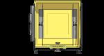
I've attached a couple newer photos and a render of an ultralight 8x10 design I'm working on that uses the knobs.
David
Comments and critique always welcome.
Thank you so much for all the clarifications. However I am still confused about something. Just to make sure, the system can be decomposed into these pieces: frame (it can tilt), rise-fall piece (where the hollow screw is attached to, the piece that has the lugs), slotted piece (this is what allows to change the rise/fall) and finally the double knobs. Now, from my understanding of what you said, the tilt screw runs through the unthreaded bore in the larger screw, and then you thread in a threaded insert inside the frame when you want to lock the tilt. This means that what prevents the frame from rotating is the pressure exerted by the outer tilt knob on the rise/fall inner knob. But this means that to change the rise/fall, you need to unscrew the tilt screw too, right? Because if you try to unscrew the rise/fall knob you will find resistance from the tilt knob, no? Am I missing something?
Sort of. The tilt on the camera frame screws though a hollow cylinder (un-threaded interior), so the bolt binds the frame to the cylinder.
The cylinder (with anti-twist lugs) passes through the slot in the standard that provides rise/fall. The outside of the cylinder is threaded, and typically has a flange on the end between the standard and the frame. There is a knob with a through hole that screws onto the outside of the cylinder.
By tightening down the knob on the outside of the cylinder against the standard, rise/fall is fixed by friction with the flange on one side. The bolt through the interior of the cylinder controls the tilt by friction with the other side of the flange. The two controls are independent - provided the cylinder cannot twist in the slot in the standard.
Note the flange and anti-twist lugs - you need something like that to restrict the motion and forces so that each control only does one thing.
Example:
My Intrepid 8x10 mk1 has an M6 bolt doing both tilt and rise/fall on the front. To split them, I need a flanged tube with M6 clearance through it, and threaded on the outside, probably M8 or M10. Then I need a through-hole knob with M8 or M10 thread for the rise/fall, and an M6 knob with bolt to do the tilt. The front standard will have to be replaced so that the tube will pass through. I would need to attach lugs to stop twisting, or 3D print a carrier (a bit like a classic keyhole shape), which would probably require the slot in the front standard to be a bit larger than the tube.
I've thought about it, but it is not critical enough for me to put it at the top of my task list 8-)
I think I understand how the rise/fall works (also confirmed by your comment). You say that The bolt through the interior of the cylinder controls the tilt by friction with the other side of the flange, but I just cant figure out clearly how this works. As of right now, I understand that this bolt threads INTO the frame, because the frame has an insert. This makes the frame able to rotate around this bolt, which basically turns into an axle which can freely rotate inside the smooth cylinder threaded only on the outside. However, the only way that I can think of how to stop the rotation is to screw this bolt so much into the threaded insert in the frame that the knob to which is attached on the outside pushes on the other inner knob and then it is this friction that keeps it stable. Can you confirm with a yes or no if what I am saying is correct? Now, if this is correct, then I do not see how the inner knob can freely rotate when the inside bolt is tight, because trying to unscrew this inner bolt will meet resistance from the outside knob. In other words, I can control tilt while maintaining a fixed rise/fall, but the opposite is not true (i.e. I cannot change the rise/fall without also unlocking the tilt). Maybe what I am saying is wrong, but I really dont see where else could the bolt inside the cylinder push that does not interfere with the inner knob.
I'll try to attach a video, which may help. As Graham Patterson explains, tilt is locked (by friction) to both ends of the lugged hollow bolt head; rise/fall locks (by friction) to the standard. Because the end of the hollow bolt is proud of the rise/fall lock wheel (even when rise/fall is unlocked), rise/fall and tilt can adjust independently. In practice, since the slot in the standard has a little clearance around the lugs, the frame will wiggle a bit around the tilt axis with rise/fall unlocked, but you'd want both knobs locked down before taking a picture in any event.
I assume the knobs on a Chamonix or Intrepid work the same way as the one I made, since it's the simplest (and therefore least expensive) way to do it. At least that I could figure out.
https://youtube.com/shorts/tQirltEJIIY?feature=share
Last edited by DDrake; 26-Mar-2024 at 07:18. Reason: clarity
David
Comments and critique always welcome.
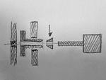
My version of the knob doesn't have much bearing surface between the back face of the tilt knob and the end of the hollow bolt. Something like a cone-shaped washer between them would probably help. I've attached a quick sketch—note proportions aren't very accurate, the standard isn't shown, and spacing between threads is exaggerated for clarity.
Attachment 248322
David
Comments and critique always welcome.
The Forum software does not like the link.
There will be differences between a purpose designed arrangement and a retro-fit (which is the only case I have considered, not having a camera with a combined control).
If it help to visualize, the tube for the tilt has a large washer fixed (welded, or machined) to one end. This washer clamps to the frame of the lens panel or camera back using a bolt through the tube. So long as the tube has lugs to prevent significant rotation in the standard, clamping this controls tilt. This still allows the tube to move in the slot in the standard. The outer threading on the tube allows a knob to clamp the standard between the knob and the washer, this controlling rise/fall. One knob has a through threaded hole (for the rise control) and the other knob has a fixed bolt (for tilt control).
Let me try again:
David
Comments and critique always welcome.
 Posting Permissions

 Reply With Quote
Bookmarks