
We're using 60 RGB LEDs per meter ribbon:http://www.leevalley.com/en/hardware...,70322&p=70326
The controller is:http://www.leevalley.com/en/hardware...,70322&p=70327 We're using the one with three knobs.


We're using 60 RGB LEDs per meter ribbon:http://www.leevalley.com/en/hardware...,70322&p=70326
The controller is:http://www.leevalley.com/en/hardware...,70322&p=70327 We're using the one with three knobs.
You often feel tired, not because you've done too much, but because you've done too little of what sparks a light in you.
― Alexander Den Heijer, Nothing You Don't Already Know
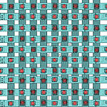
Yes I have the same it is crazy bright! Here is the sketch I made to maximize leds per square mm. I am looking forward to seeing this in action.
I realize this should go into the light sources thread but I'm going with the flow here. Ludvig or anyone else, do you have any ideas on how to make (3) three digit readouts for the R,G and B values work with this RGB LED Ribbonflex strip? So far I've heard from a couple of companies I've put that question to that it'll require a DMX controller, which seems like a replacement for the knob controller we're using for starters, no harm there as long as we can input values during the testing phase, until we can establish working presets. The stock controller is analog and I wonder if there's a converter/display type doodad that can help. The only thing I've found so far is a single readout DMX controller: http://www.chromationsystems.com/sto...51r9k6c2rqjar6
I'm still working with Jeff from chromationsystems.com and will report any news.
I've also found this tidbit:
http://log.liminastudio.com/itp/phys...rgb-led-by-hue
which represents another approach but that may be too much for the circuit as it stands, pretty much out of available pins without going to an Arduino Mega or similar.
Well if you want to control red green and blue with PWM from an arduino and control the light levels on r, g and b with digital control from 0-255 you could do it with three power transistors and one of these lcd shields with buttons http://www.adafruit.com/products/772. That would use up 5 pins. 2 for the display/button shield and 1 each for the R, G and B transistor. Also you could control everything else like speed on motors delays etc.
Ludvig
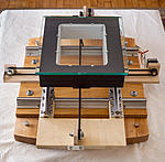
Here's my XY stage before I cover everything with wires. It has 8" of movement left to right and 12" of movement front to back. The lighted area of the light source is 6"x8", which should be enough to scan 5x7" film. Building a light source for 8x10" was more than I wanted to spend on a prototype. Currently, there's a 12" x 12" piece of plate glass sitting up top. I'll be able to switch out a glass plate for wet scanning and P99 acrylic for dry scanning. Negative masks will be made from black ABS, and there will be stops so that it'll be easy to align the scanning surface and masks.
You often feel tired, not because you've done too much, but because you've done too little of what sparks a light in you.
― Alexander Den Heijer, Nothing You Don't Already Know
Peter, that looks quite nice. I assumed you were using the light source under the glass but I don't see an aperture in the base so how does this function - especially with a large uniform 6X8 inch illuminator? Maybe I see a smaller aperture that is sufficient to cover only a full frame DSLR but is partially obscured by a stepper belt. The DSLR stays fixed over the smaller aperture? Those stepper belts seem to interfere with the illumination path.
Do you plan any stage leveling mechanism?
Nate Potter, Austin TX.
Hi Nate,
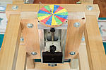
Regarding the light source, here's the LED plate:
It will be installed at the bottom of the white painted box, just above the belts. (Well, hopefully just above the belts.) The interior of the light source, which is currently white, will be covered in reflective aluminum tape. (Tests show that doing so really helps with edge light falloff.) A 3/16" thick piece of white acrylic will sit in recessed opening.
Regarding leveling, rough leveling will be accomplished with 3/8" bolts. You can see them in the picture. I drilled and tapped holes in the thick maple slab for this purpose. For fine leveling, all major parts are bolted, often with t-nuts. As a result, shims can be installed in lots of places.
You often feel tired, not because you've done too much, but because you've done too little of what sparks a light in you.
― Alexander Den Heijer, Nothing You Don't Already Know
Why do you need/want the light source to be so large? If the X-Y table is going to move the negative around, then the even area of the light source only needs to be as big as the "shot" size, and it can hold still underneath the camera lens. What am I missing?
Science is what we understand well enough to explain to a computer. Art is everything else we do.
--A=B by Petkovek et. al.
You're not missing anything. It could be done that way, and that's what I did with an earlier prototype. I went this way, though, to minimize the chance of repeating patterns in the final stitch due to small irregularities in the light source, irregularities which would be repeated in each tile of the stitch.
You often feel tired, not because you've done too much, but because you've done too little of what sparks a light in you.
― Alexander Den Heijer, Nothing You Don't Already Know
Z-axis:
You often feel tired, not because you've done too much, but because you've done too little of what sparks a light in you.
― Alexander Den Heijer, Nothing You Don't Already Know
 Posting Permissions

 Reply With Quote
Bookmarks