


This post is both an idea about how to implement pre-exposure and if you like, build a circuit to help. I built this about a year ago and it has worked very well. If you work with electronics, this should be pretty easy, but requires that you know basic parts ordering, soldering of parts, and simple packaging.
I get a lot of good from pre-exposing prints. I find it a very handy technique in the darkroom. Besides pre-exposure, I've heard it called 'bump', 'flash', post-exposure. There must be other terms. The point is to give a threshold exposure to your print with green light to bring in those highlights that are too dense to be registered on the printed image otherwise. I've always found it inconvenient to implement until I made this little gadget. Nothing fancy, mind you, just a green LED that I mount under the filter holder (brown masonite in the picture) below the lens on my enlarger. It's there all the time, ready to go. A very dim green LED that I set for 1 to 10 sec. Since it is located near the lens, I can dodge / burn the flash easily. It doesn't take up other space in my darkroom.
Those of you familiar with the "555" timer will recognize the circuit. R1, R2, and R3 are all quarter watt resistors. R3 you'll need to play with to get the right brightness from your LED. These days with LEDs so efficient, just a milliamp or two is enough. R4 is a potentiometer or 'pot': resistor with a knob to adjust the ON time. This circuit will give you 0.1 to 10 seconds. C1 is a film capacitor. It really needs to be film. It's $2. C2 should be X7R type at 25V or greater. D1 is the LED that gets mounted beside your enlarging lens. Pick a 20 mA (or less) type green LED in a package you like.
Power is from V1. I use an old cell phone wall wort. It can be anything from 5V to 15V. At 16V, U1 will be damaged. The LED is shown in a little black thing that I had. I put a piece of diffusion material over it. Very primitive. I used a T-1 3/4 LED, but I sanded off the end and made it flat and diffuse so it didn't project an image of the LED chip.
Pic 1 the schematic
Pic 2 shows the LED mounted under the lens
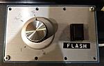
Pic 3 the box
If there is interest, I could add a basic parts list to order from Digikey. Figuring out the box and wall-wort, you're on your own. I'm sure others here will have some grand additions and construction ideas.

 Reply With Quote
Bookmarks