Results 1 to 4 of 4

Thread: Jobo CPP-2 Temperature board - question for experts

  1. #1

    Jobo CPP-2 Temperature board - question for experts

    OK, this is really a question for anyone who has full refurbed a CPP-2 or might have one on a bench where they can measure some voltages. For the rest of you this is probably going to read like gobbledygook.

    I have an old CPP-2 which is mostly working, except that the temperature display is '---'. (It was working until very recently).

    Normally this would be a sign of a failed temperature probe but I don't believe it is in this case (I might be wrong!) as all the voltages seem to read within the specs on the schematic shown in the online service manual. The probe shows a resistance of about 800ohms at 15C.

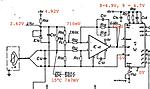
    The issue appears to be with IC45. I am getting around 100-150mV on the input to pin 11 which is within the 0-0.5V limits on the schematic, with pin 10 at 0. However the chip is putting out a signal of negative signal out of range.

    The one weird thing on my board is that pins 8 and 9, the zero offset, which are both linked to V+ by identical resistors, are at 4.9V and 4.7V respectively, ie pin 8 appears to be shorted to V+. However there's no sign of a short on the board and all the resistances measure correctly.

    So my questions to anyone who might be able to answer them...

    -- what would be a sensible voltage across pins 10 and 11 of the IC? From the datasheet it looks like -99mV to 999mV.
    -- what should pins 8 and 9 be reading at?
    -- what would be a sensible resistance for the temp. probe?

    My working assumption is that IC45 has failed but I'm no electrical engineer. I attach a schematic with my measured voltages. All help gratefully received, and no, I'm not in the market for a CPP-3, thanks.

    I should add that the outputs appear to be working fine, as do the LEDs.

    Click image for larger version. 

Name:	185506141_10158404372213893_6270403669352713448_n.jpg 
Views:	26 
Size:	42.7 KB 
ID:	215834

  2. #2

    Join Date
    Jun 2014
    Posts
    2,084

    Re: Jobo CPP-2 Temperature board - question for experts

    Could you upload the full schematic please?
    What types are IC46 & 45?
    I assume 45 is a 7-segment driver? Or is it an ADC?

    Quote Originally Posted by JohnBrownlow View Post
    -- what would be a sensible voltage across pins 10 and 11 of the IC? From the datasheet it looks like -99mV to 999mV.
    Likely around 0V, but I'd need to see the rest of the schematic and it would also be good to know the values of R61, R62 & R66.

    -- what should pins 8 and 9 be reading at?
    Most likely close to 5V, but I'd need a datasheet and ideally also the values of R56 & R57.

    -- what would be a sensible resistance for the temp. probe?
    Depends on the sensor used. Could be around 100R, 1k or 10k...they come in all sorts of flavors. Your measured 800R could be reasonable, but again, it depends on the type used.

  3. #3

    Re: Jobo CPP-2 Temperature board - question for experts

    Quote Originally Posted by koraks View Post
    Could you upload the full schematic please?
    What types are IC46 & 45?
    I assume 45 is a 7-segment driver? Or is it an ADC?


    Likely around 0V, but I'd need to see the rest of the schematic and it would also be good to know the values of R61, R62 & R66.


    Most likely close to 5V, but I'd need a datasheet and ideally also the values of R56 & R57.


    Depends on the sensor used. Could be around 100R, 1k or 10k...they come in all sorts of flavors. Your measured 800R could be reasonable, but again, it depends on the type used.
    Hi, thanks for the response. IC46 is a plain old opamp, a CA3140E
    https://www.futurlec.com/Linear/CA3140E.shtml

    IC46 is an A/D converter for a 3-digit BCD display that drives a 3-segment LED array
    https://datasheetspdf.com/pdf/496986/Intersil/CA3162/1

    Full schematic I'll dig out but it doesn't tell you a whole lot more.

    I made some progress with this today. I built the circuit in a simulator and my values all seem to make sense. I think the problem is definitely around IC46. My current suspect is not the chip but the integrating cap C49. When I briefly put a 220 uF cap in parallel with it by hand suddenly the display sparked into some kind of life. If the integrating cap was toast then it would explain the system reading low I guess. I'll investigate further.

  4. #4

    Join Date
    Jun 2014
    Posts
    2,084

    Re: Jobo CPP-2 Temperature board - question for experts

    Yes, open failure of c49 is a likely cause. You could work out based on the datasheet if this does indeed result in a negative out of range error as you're seeing.
    The problem I see with this design is that the calibration is quite dependent on the value of c49 (typically 270nF according to the datasheet) and ceramic capacitor tolerances are typically 5-10%, so that induces a pretty big error as a result of hardware limitations. After replacement of c49 be sure to recalibrate the display by adjusting p4 and a verified temperature probe/thermometer.

Similar Threads

  1. A question for our resident sensitometry experts
    By robshepherd in forum Darkroom: Film, Processing & Printing
    Replies: 7
    Last Post: 29-Apr-2020, 04:59
  2. Another Petzval lens question to the experts
    By seven in forum Lenses & Lens Accessories
    Replies: 10
    Last Post: 1-Nov-2015, 13:11
  3. A question for the brass lens experts
    By Ray Bidegain in forum Lenses & Lens Accessories
    Replies: 4
    Last Post: 19-Feb-2009, 22:21
  4. A question for the digital experts here
    By chris jordan in forum Digital Processing
    Replies: 37
    Last Post: 14-Nov-2006, 11:13
  5. ImagePrint Experts Question...
    By jim kitchen in forum Digital Processing
    Replies: 24
    Last Post: 13-Sep-2006, 20:34

Bookmarks

Posting Permissions

  • You may not post new threads
  • You may not post replies
  • You may not post attachments
  • You may not edit your posts
  •