
I'm in the UK, and am clueless about what threads were commonly used in the US... Does anyone know what thread standard (or angle) was used for Ilex shutters?Originally Posted by Whir-Click

I have an Ilex #5 shutter without a flange / lock ring...


I'm in the UK, and am clueless about what threads were commonly used in the US... Does anyone know what thread standard (or angle) was used for Ilex shutters?
I have an Ilex #5 shutter without a flange / lock ring...
My measurements suggest that you are applying very reasonable logic. However, in the early days of lens production, standards seem to have been a real rarity so my guess is that makers simply built a lens and used a fine thread on the final diameter. Certainly, one or two that I have measured look suspiciously like they were in 1/64". I also have several flanges from the same (model of) lens which vary not in thread pitch but in diameter and enough to mean that one flange will fit one lens but not the others but the other flanges fit all lenses. This may be a QC issue, but the fact that one flange is marked with the lens serial number makes me wonder if they were cut individually. I am starting to think that this might be a minefield. Perhaps the best approach would be to come up with a Fade Mecum style document which lists lens threads by maker - but its a massive job and needs substantial breaking down.
's Avatar")
Here's some summarised information about US threads: https://www.sizes.com/tools/thread_american.htm
Main difference on older threads is that British use 55 dgr and USA/Can 60 dgr angles, which changed after WWII - both would use 60 dgr.
Don't have info about US shutters, but the post from Whir-Click mentions the #5.....
The US threads seemed to be mostly truncated at the top of the crest....
The only reason for me to start this thread was to see whether fellow members would like the idea to exchange their inventory of spare mounting flanges/rings in order to be able to try to get a match with a lens, for possible trade.
But I'm sure that trying to make a list for all known lensmakers seems not at all feasable (especially since spare rings usually don't have an indication about its maker), and IMHO doesn't serve a practical purpose......or am I missing something?
Ron, a laudable aim, and it has also sparked discussion about these things... very useful in itself, and surely the way that research develops? One thing leads to another...
As PKG suggests, a separate endeavour might be to record, categorise and thus start to recognise types of thread used. If nothing else it would be good to see if a pattern emerged, or if it was all just random chaos. It would make more sense to sample lens threads (rather than flange threads) as the maker is often known, and surely a manufacturer must have standardised on a thread within their own company - or hopefully at least within a production run of certain lenses. (Wikipedias History_of_standardization of threads). Measuring thread angle would be tricky, although external threads are probably easier.
It would be interesting to hear from someone who uses (or has used) manual (=not heavily automated) metal working lathes, and get a view on how a lens thread and matching flange thread might be cut, what decisions would have to be made, especially on the equipment of the time.

Side note about lens flanges and retaining rings: Good place to find them is on eBay. Every now and then someone puts up for auction a box of many of them. Years ago bid on and won a box of dozens of them for little more than the shipping costs. Forgot what the seller called them, but it wasn't "lens flanges" or "retaining rings" but something like a "collection of thin threaded rings".
A few years ago I contacted the RAS [Royal Astronomical Society] regarding Whitworth threads used in 'old' lenses. It seems that the Whitworth thread was used but slightly different from the standard thread. I can't remember, or find the relevant RAS archive, but it was to do with either the angle or depth of the thread form.
Regards
Tony
Threads are cut using a lathe whose tool is mounted on a leadscrew, with the leadscrew rotation geared to the spindle so that the tool moves along the piece as the piece rotates. Choosing the gear ratio controls the pitch of the thread. (Of course, this brings up a philosophical question: how were the threads on the first leadscrew formed? Probably by the chicken that laid the first egg, or by hand.) Practical screw cutting lathes have been around since the early 19thC, although I was a bit surprised to read that drawings of the idea go back at least as far as Leonardo: https://en.wikipedia.org/wiki/Screw-cutting_lathe
The subtleties in cutting a thread include getting the thread angle and depth right, and starting the cut in the same place as you make multiple cutting passes with the tool. Well-equipped machinists have sets of depth and thread gauges to measure the threads. Someone with a lot of machining experience (Bernice?) could explain more.
Cutting threads properly seems to be a popular topic among home machinists - there are a lot of youtube videos on the subject to show how it's done.
Last edited by reddesert; 16-Aug-2020 at 00:58.
There is a guy on a facebook brass lenses group that is making flanges. They seem to be working for those that bought them. I talked to him about making a flange for a rare lens of mine, but without having to send the lens. My idea is to use Cerrosafe, a low melting point metal that is used for casting and measuring things accurately. I'm going to make a cerrosafe dummy flange, send it to him, and have him replicate it in brass or alum.
Garrett
flickr galleries
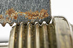
Here is a shot illustrating the problem of measuring threads. The lens is an ~1860 Petzval which arrived minus flange. The gauge shown is a 22tpi Whitworth aligned with the flange thread on the lens which shows wear. I am reasonably confident about tpi and that the thread is Whitworth because examination shows wear on the camera side of the lens which is where I conjecture it would be most subjected to higher forces upon mounting rather than removal. The brass is probably fairly soft so the thread has rounded off as well as worn on one side. Despite this there are sufficient points of coincidence between the worn thread and the gauge to suggest they are the same thread. Or at least that's my take. Can anyone with more experience of thread measurement comment please?
Last edited by pgk; 17-Aug-2020 at 05:34.
 Posting Permissions

 Reply With Quote
Bookmarks