
Yes, but...Originally Posted by dfroula

I believe one could plug a cord into the flash gun the other end of which plugged into the solenoid which had a pair of metal pins for the purpose.


Yes, but...
I believe one could plug a cord into the flash gun the other end of which plugged into the solenoid which had a pair of metal pins for the purpose.
Some flashes did have a button to remotely fire the electronic shutter, but the power sources for the flash bulb and shutter solenoid were always separate. A special "Y" cord was used that split the three-pin plug that mated with the camera socket on one end and two sockets on the flash tube, one for the remote trigger button, the other. for the flash contacts from the shutter.
With such a flash, depressing the remote shutter button on the flash body completed the circuit of the internal 45 volt camera battery/capacitors and the trigger solenoid. When the shutter triggered, the internal shutter contacts completed the circuit of the batteries in the flash handle and the flash bulb; two separate circuits linked mechanically at the shutter.
My HR flash has a cord with three pins for the camera socket, but only a single dual-prong plug at the other end for the flash bulb circuit to the shutter - no remote button.
Are you talking about using the Y-cord or some other configuration? I've used the Y-cord for bulbs and shutter release but it still needs the battery in the body to trigger the release. The flash handle just provided a remote/alternative switch.
If you are suggesting the possibility of feeding current into the 3-hole socket on the side of the body... I'm all ears. Have thought similar but never examined the wiring diagram to determine if that would work or not. To get 22.5V one would have to use the Graflex B-C which, unfortunately, doesn't eliminate the need for a 412 battery. But if you are thinking B-C current going out the "remote" plug and into the body via a separate cord... I wondered the same thing.
I agree with you about the "Y" cord used with flashes with the alternate shutter button.
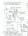
Yes, you can feed 45 volt shutter battery power via the rightmost socket hole in the camera side and the lower solenoid terminal on the lower front lens standard (back side with small nut), but you have to supply your own current limiting resistor as this bypasses the internal resistor. These are the only access points for feeding external power to the trigger circuit, other than the battery contacts. The positive side of the circuit cannot be accessed from any of the three socket holes.
Basically:
Remove batteries from battery compartment or place tape over the battery door contacts. Connect the negative side of the 45 volt battery/power source to the right-most terminal of the flash socket on the camera body through (in series with) a 2.7 kohm 1/2 watt resistor. Use a finishing nail or 14 gauge solid wire as a contact post. Connect the positive side of the battery stack directly to the lower terminal on the right rear bottom of the lens standard. Look for two small nuts holding wires from the solenoid. These are the terminals from the solenoid. Don't omit the resistor or the capacitors and/or solenoid may be damaged. This method of testing bypasses the internal resistor, so you must supply one. Works great for testing. You can verify my connection suggestions by referring to the schematic.
However, you mention feeding 22.5 volts externally through the side connector for flash power, if I read your comments correctly. I guess that is possible, but you'd have to run a jumper wire inside the flash gun battery tube to short the contacts to get continuity, or it wouldn't work. I see no adavantage to using an external flash supply. Why not just use D cells or a B-C adapter, since they are cheap and available?
Annotated schematic attached.
Well, my 20 CR2032 lithium coin cell batteries arrived today. They were a quality Panasonic brand. Either Sony or Panasonic CR2032s should be used for this project, as their capacity is least affected by higher intermittent current load.
I prepared a battery pack of 4 stacks of 4 cells each. This gives a nominal voltage of 3x16 or 48 volts. The initial voltage is actually 50 volts, but quickly drops to 48 after a few shutter activations. Although a bit higher than the 45 volts provided by the regular carbon zinc natteries, this voltage is within the tolerance of the capacitors and gives a slight extra punch to the shutter activation.
I soldered wires directly to the cell for the + and - wires as well as to the cells that bridged the individual stacks. There is a good tutorial on how to do this (not mine) on YouTube:
Be sure to clean all solder flux off of the battery after soldering.
I prepared 8 of the 16 cells by soldering. I soldered one red wire to the + side of one cell. I soldered a black wire to the - side of another cell. I then prepared 3 pairs of cells with a short piece of wire soldered to the + side of one cell and the other end of the wire to the - side of a second cell. These three pairs are used to bridge between the stacks of 4 cells each.
I then started with the cell with the red wire and placed 2 cells beneath it in the proper + to - orientation, ending with the + side of one of the soldered together pairs. I taped this stack tightly together with stretchy black electrical tape to press the first stack of cells tightly together. I then did the same with the second, third, and fourth stacks, ending the fourth stack with the cell with the single black wire. Of course the - to + polarity between each cell must be maintained throughout.
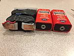
Finally I used a wrap of tape around the circumference of each stack so the stacks would not short to one another when pressed together. I then used a wrap of electrical tape to hold together each pair of stacks in a 4x4 configuration. The final assembly should look like this:

You can see the dimensions of the pack are similar to the two original Eveready 412 cells side by side.
Next I had to fabricate terminal strips to make contact with the terminals in the battery compartment. I used a few small pieces off copper clad circuit board, but the same could be done with brass or copper sheeting. I soldered the red and black wires to the pieces and mounted them on one end of the pack using foam tape to provide some pressure against the contacts. I put a few strips of foam weatherstriping on the opposite side of the pack so pressure would be place against the contacts when the battery door was in place.
I carefully inserted the pack into the compartment of the camera, aligning the contact plates on the pack with the contacts in the compartment. I replaced the battery door. being sure the foam was thick enough to put pressure on the terminals and maintain good contact.
The pack worked perfectly, with plenty of authority. Voltage seems to recover to a nominal 48 volts a few seconds after each shutter activation. I was able to monitor the battery voltage from outside the camera using the same connections I used to apply external voltage to the camera, described in an earlier post. The lithium cells have a capacity of 240maH compared to the 140maH of the Eveready 412s, so battery life should be good if your camera's capacitors are in good shape. BTW, capacitors need to be "reformed" if they have been sitting unused for many years. Just placing the correct voltage in the camera and leaving it sit for a time may recover capacitors which seem to be bad or have high leakage. Worth a try, as disassembling to get to the capacitors involves pulling the pointer off the rangefinder computer and getting it glued back in the correct position.
Check the video of the pack in operation at:
https://youtu.be/D9gimnnFl1k
Be cautious about applying excessive heat when soldering as it is easy to ruin a cell, even causing it to burst. Wear eye protection and test the voltage after cooling to be sure the voltage is OK. Also, take especial care NOT to short the completed pack, as this many cells in series packs a bit of a punch and could build up heat quickly. The internal resistance of CR2032s is pretty high, so fire or smoke are unlikely, but some of the cells in the pack will be damaged, degrading performance of the entire pack.
I tried connecting the flash cord on the camera side to my two Speedotron 4800ws packs that I use for wet plate portraits. I can press the red button on the camera to trigger the shutter, in turn closing the shutter flash contacts and firing the two optically slaved Speedotron packs. Works great!
Well that's very interesting!
Diagram of cell stack wiring. You can see where the three pairs of cells that are wired together are used.
Last edited by dfroula; 14-May-2017 at 08:58.
I must apologize, I did a bit of reading and some of the flash units used with the Speed Graphic (external low voltage solenoid) did indeed power the shutter solenoid and pop the bulb using the same 2 or 3 D cells in the flash holder. The required momentary current required was about 7 amps, so battery life must for reliable operation must have been quite short. It appears these external "Synchronizer" units were used with shutters without internal synchronization contacts. The synchronization, apparently, depended upon very precise adjustment of the low-voltage solenoid such that the bulb fired and the shutter opened with the correct timing. That must have been incredibly difficult to adjust without proper equipment.
The Super Graphic lens board has contacts that connect to the coaxial connector on the shutter and feeds the connection back to the flash gun, so proper operation is not dependent on the mechanical adjustment of the solenoid.
I assumed the button on Synchronizer flash units simply fired the shutter, which in turn used its contacts to trigger the bulb, but it looks like it was all "open loop" at the flash unit.
The flash unit I have does not have the Synchronizer capability, just household prong sockets for shutter and two slave flashes - no shutter button, which is fine for the Super Graphic.
At least I think that's how they worked, based on some additional reading. Corrections welcome.

First, thank you for your contributions here.
The synchronizer/solenoid was not difficult to time. The adjustments you see in the cap were largely to fit the reach to the shutter lever. The big bulbs began to peak with a 1/50th of a second delay (20 milliseconds) and using a conservative shutter speed helped, too.
(aside: I think I have worked out a way to wirelessly fire those solenoid linked shutters using original Graflex flash gear.)
do tell...
 Posting Permissions

 Reply With Quote
Bookmarks