
Originally Posted by
polyglot

A note about the ballast temp though - that 70C specification is the max case temperature that they can survive and is absolutely no indication of how hot they will actually get nor does it say anything about the heatsinking required. The actual temperature attained is a function of not only how much power they dissipate but also how you heatsink them. If you put them in a sealed box, the temp will climb past 70C and they will fail sometime after it goes above 70C. If you put them in a well-ventilated box, they will probably stay within 10C.


 Reply With Quote
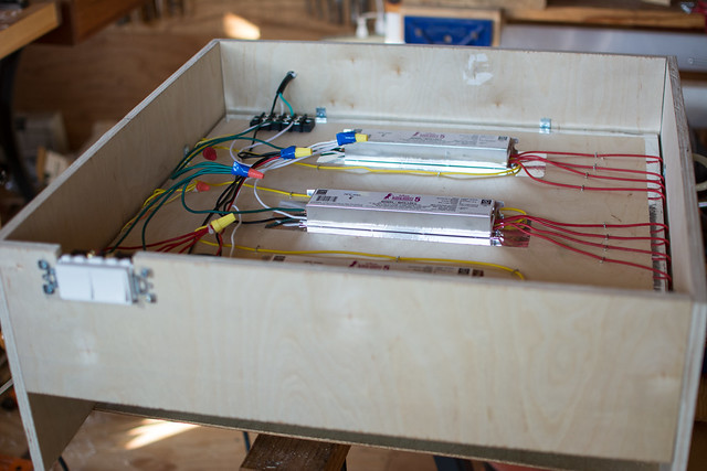


Bookmarks